

I’ve added 2 screw holes to the side of the platform – 5/8″ in from the back, 7/16″ spacing, just about center of the 1/4″ (top) piece, and used 2 #6 1/2″ wood screws to mount the servo. I used a 1/8″ piece of ply (needs to be 1/8, 1/4 is too thick) cut like a fork – just a bit over 1/4″ gap in the tines. The mounting hole is 7/32, and just press fits in place – very securely as it turns out.

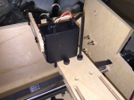
The timing (drive) belt is spliced by cutting a short piece from the belt and pressing it into the indent, teeth up. The ends of the actual belt then lay teeth down, intermeshed with the splice. The design has the depth of this channel exactly the thickness of the belt splice, so fastening the two carriage pieces to the linear bearing holds the whole assembly together.


Finally, I added a 1/8″ piece of ply to the face of the mounting head, with a 1/2″ diameter hole centered in the original hole. That lets me use the dremel hand piece, and the scew on head then clamps the hand piece to the sub-board. (The threaded head on the hand piece really does need a 1/8″ piece for this).


 Next I will testing the carriage to make sure the servo has power to raise and lower the dremel hand piece – and to see how it does running back and forth with the drive assembled. Then we get to have a bit more fun. The dremel power cord is plugged in through a power switch that is actually controlled from the arduino.
What could go wrong? power tool…. check …. full house electricity … check … hooked up to a cheap micro-controller … check … programmed by me … check.
Should be an exciting holiday weekend!

Pingback: Pen Decorator – the drill platform | Brian's Workbench